There are also third party XG and XD winders. [Christopher G. Mullin]
| 5.1.1 Winder G | |
|---|---|
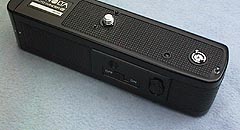
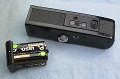
| The controls consist of just an on/off switch and a turn/push button to operate the rewind button on the base of the camera. |
| Here the battery holder (4 x AA) is shown removed and you can see the metal-threaded tripod socket in the centre of the base. Note that the tripod socket is slightly off the lens axis. |
| Whilst Winders D and G are very similar, there where slight differences in the location of pins and electical contacts on the base of the cameras making them non-interchangeable. A version of the Winder G was made that also powered the camera's internal circuits via a protrusion from the top into the button cell compartment in the bottom of the body - I believe the designation was Winder GP | |
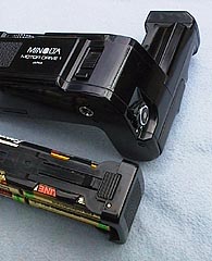
| 5.1.2 Motor Drive 1 (MD-1) | |
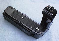
| Ths view from above clearly shows the grip and the contact pins. Sadly motorised film rewind was not a feature. Attachment to the camera was via a large serrated wheel; as with the Winders, nothing had to be removed from the camera to enable fitting. |
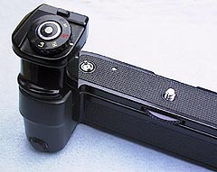
| This front view shows the 'speed' control on the top of the grip. Positions are Lo (2 fps) Hi (3.5 fps) Off and S (single frame advance). You have to push down the little rectangular button to turn the control. The maximum frame advance rate was controlled by the camera, being dependant on the shutter speed. The shutter release is touch-sensitive, just like the ones on X- series bodies. |
| This view shows the battery holder removed (8 x AA) and the extra shutter release button on the end, making vertical shooting easier. It also shows the odd position of the tripod socket, which can make copy stand work a little awkward. |
| Both Winder G and MD-1 seem happy with Energizer Lithiums - they certainly save a lot of weight! [Chris Valentine]. There are also third party XG and XD winders. [Christopher G. Mullin] | |
| Photos above taken with a digital camera, © Chris Valentine 1998. | |
First - opening it. Remove both pieces of the self-adhesive black leatherette, the two rectangular metal clips (which will probably remain stuck to it) and the 4 screws farthest from the battery end (the last screw is just for the battery compartment clip). You do not need any force to now separate the two halves of the drive. Just don't loose the little screws!
There are 4 wires connected to the battery clips:
The two at the back are connected together with a yellow wire - this goes nowhere else.
At the front, the bottom contact has a red wire.
At the top, the contact has *both* blue and black wires.
Although it has only two poles, the switch has three wires.
On the left contact, nearest the battery go white and blue wires.
On the right contact is a red wire.
The LED has orange and green wires, but I don't know which is anode and cathode - I presume the latter is green.
The motor itself has a blue and a red wire coming out of it.
The ciruit board is very small and sits under the motor. The most likely candidate for failure is a little PCB-mounted relay.
While you've got it apart, you might as well give the gears a squirt of a dry-film lubricant, such as PTFE. Wipe off any excess. Clean the battery contacts too, coz you can't get at them when its assembled.
Reassembly: slide the two halves together, remembering to fit the switch panel in place. Tighten the 4 screws then reapply the leatherette with the metal clips.
[Chris Valentine]
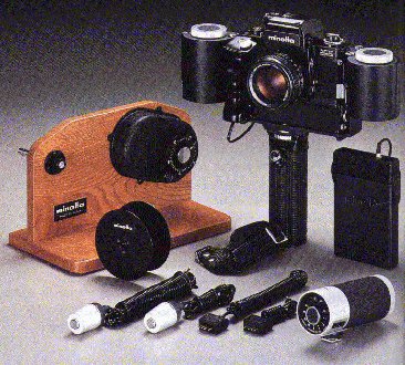 A 250 exposure bulk film back, together with a wooden (!) film loader, was available for the XK-M (motor) professional SLR.
Some of the XG- XD- and X- series had interchangeable backs - this feature was removed from the very lowest models in the ranges to keep the cost down. In common with the 'naming' of the Winders: Models XD- could take Data Back D, Models XG- took Data Back G and Models X-570 and X-700 took either Quartz Data Back 1 or the Multi-Function Back - more data and photos of these are on my WWW pages. [Chris Valentine]
On Thu, 25 Feb 1999, on the MML, Raphael J Cohn (t03rjc@abdn.ac.uk) revealed that the MFB can in fact be used on XG bodies that had an removeable back (not all did).
External links:
Data Backs
MultiFunction Back
As well as conventional mechanical releases and both long and short electrical release cables, X- series could be remotely triggered by a near-infra red beam system. Most often the transmitter and received were bought as a pair, but as the system had three channels, you could later buy up to two more receives and hence control up to three cameras from one position.
The IR-1 is identical to the IR-1n still in production for the Dynax range of AF SLRs. The only difference is the cable used to trigger the camera from the receiver. A shoe adaptor is provided so that the receiver, which has a regular ISO foot, can be mounted on the hot shoe of a Dynax camera - no electrical connections are used on the hotshoe.
External link:
IR-1 Remote System
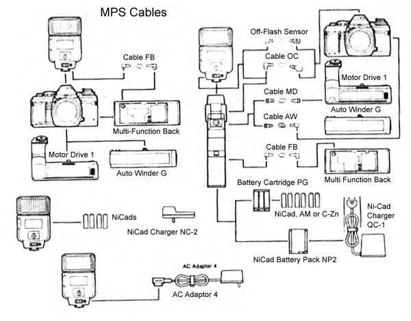
Here's a list of all the cables that were part of the original Minolta Program System (the X- series bodies, etc) and their intended function.
For the X-700 body, these lenses were designated Eyepiece Corrector Vn No.1 to No.9.
From the MML, Nick Danger (ndang@eritas.org) wrote:
The actual interior area of the correction lens is 1/2 in. x 5/16 in. That is significantly smaller than the eyepiece lens itself -- it has to be, to allow room for the plastic frame that holds the correction lens inside the eyepiece.
However, because the correction lens is closer to your eye, it doesn't seem to restrict the field of view significantly -- especially compared to viewing while wearing glasses instead of using the correction lens!
Unlike some other manufacturers, Minolta designed its eyepiece corrector lenses to clip inside the eyepiece frame, so you can still use accessories such as the angle finder that mount on the outside of the frame.
Minolta made (and still makes for its AF cameras) an expensive, quality right-angle finder which uses a prism to keep the image the right way round. The Angle Finder Vn, as its called, even has its own diopter adjustment (although its really just a focus control). This accessory can also be used on some Nikon/Kodak digital SLRs. There was also a smaller flip-up viewfinder magnifier for more accurate focussing.
Nick Danger (ndang@eritas.org) again:
However, I can't think of why I'd ever need to do this, since the diopter adjustment range of the Angle Finder is quite wide. Even if you routinely use an eyepiece correction lens for normal viewing, it's probably easier to snap it out when installing the Angle Finder.
I tried on the nearest convenient body (a Maxxum 9000) to verify that the Angle Finder Vn will in fact fit over a mounted dioptre lens. It does, but it's a tight fit (at least on this particular camera.) If I were going to use both a correction lens and Angle Finder together regularly, I'd file a bit off the face of correction lens' plastic frame to create enough clearance to slide the Angle Finder down easily.
The Angle Finder Vn also fits bodies up to and including the 800si. It is identical to that supplied by Leica [Simon Gardner].
Date: 19 Apr 2002
From: Stephen I. Molnar via ManualMinolta list on Yahoo groups:
Let's see, the PGI and II and the AC adapter pins will read the following voltages:On side +9VDC; Center pin 0 or common; other side 180VDC. Unless you measure it the right way, you will not read anything. However on the AC adapter I can measure up to 210VDC free floating voltage but as soon as any load is put on the system, the voltage drops to about 180VDC.
I do believe that all the flashes which were intended to be used with the power grips, ie: the 320 and 280 and the 360 series will charge the capacitor directly parallel with the flash's own circuitry. Unlike the 450 flash which cuts out or bypasses the 6 AA batteries in the flash and charges directly from a 510VDC belt pack. I have all these flashes and grips and I have taken the PGI apart. There is a small PC board in the handle with an oscillator a transformer and a rectifier to provide the nominal 180VDC. Since they are all interchangeable / just file off one corner from the PGI's plug / and the AC adapter was built for both, therefore I say, they both work the same way.
This is the only logical answer because the only limiting factor is the batteries internal resistance which limits the rate at which the current is transferred.
By substituting NiCads for the Alkaline batteries your recycle rate will increase. Buy using NiMh batteries this is true over NiCads again. Adding parallel high voltage (180VDC at a few milliamps) directly into the strobe's main capacitor, you can reach up to 4 flashes per second on a good day with NiMh batteries, but 3.5 for sure.
Date: Wed, 28 Jun 2000
From: Justin Bailey (red_bailey@hotmail.com)
Subject: Power Grip 1 nicads...
The Power Grip 1 uses the same NiCd Battery Pack NP-2 as the Power Grip II. Good luck finding one used without the grip, and in functional condition. The pack is a screwed-together plastic frame that holds six soldered NiCd AA cells. Thus the specification is 7,2V, the same as a 9-Volt size NiCd battery. (Without the NiCd Charger QC-1, you can rig a 9-Volt charger to work.) My NP-2 contains batteries of the Golden Power brand, type KR500AA, rated at 1,2V 500mAH (the whole pack is rated 7,2V 450mAH).Even though I have one useable NP-2, I have successfully used a 9V battery or a 4AA battery cartridge from Radio Shack, with proper spacers in the chamber to prevent the smaller units from shifting. If you could locate a Battery Cartridge PG (6AA, sold with the Power Grip II), it would be even better. Again, good luck.
If you plan to use your Power Grip 1 or AC Adapter-3 with PX-series flashes that share the same power connector, you must file off a tiny bit of one corner on the Grip connector (you will see once you examine the combination). Otherwise, I can say it works perfectly with a 360PX, and I must assume the 280PX, but not an 80PX (the foot is further back from the front of the flash).
The Power Grip 1 is more compact than the Power Grip II, which added the option of using 6 individual AAs (NiCd or not) with the Battery Cartridge PG. It also added a hot shoe, bounce capability, and a shutter release all on the grip.